Please find the instructions for the Audio Box LiPo/LCD kit installation below.
The Audio Box LiPo Update kit is compatible with both hardware A and hardware B Audio Boxes. Your Audio Box will need to be upgraded to firmware version 5.1 or newer in order to be fully compatible.
Note: Your hardware may look different than the pictures below. This can include the harness wire colors and parts on the Audio Box PCB.
Tools Required:
- Phillips Screwdriver
- 5/16" Wrench
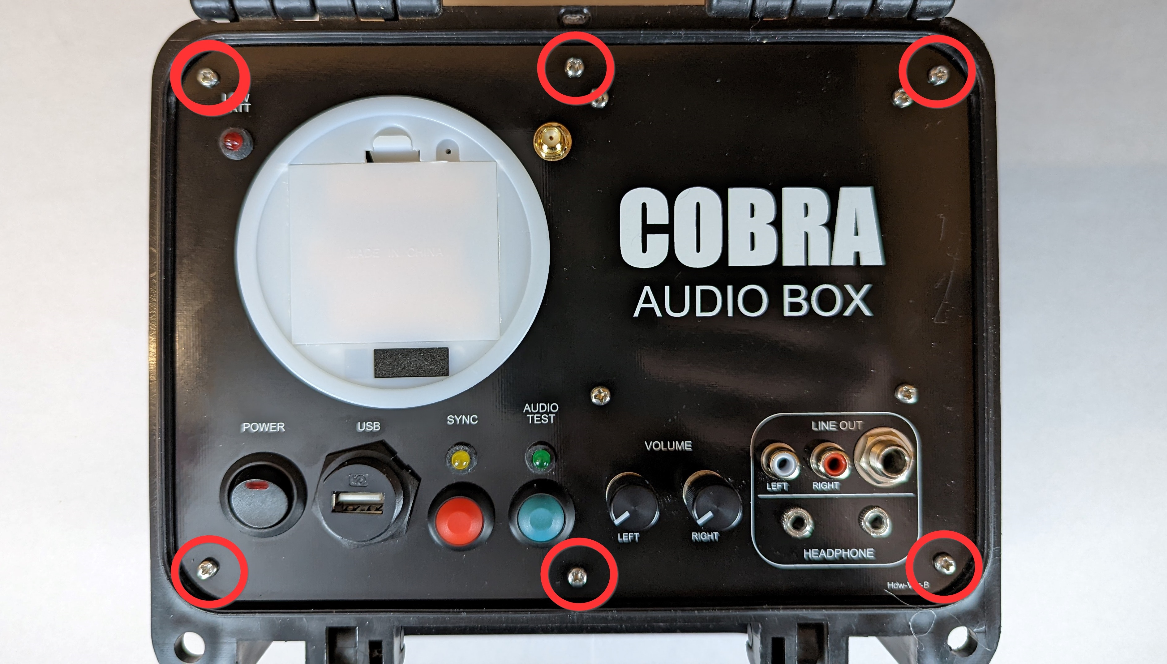
1. Remove the six screws from the front of your Audio Box.
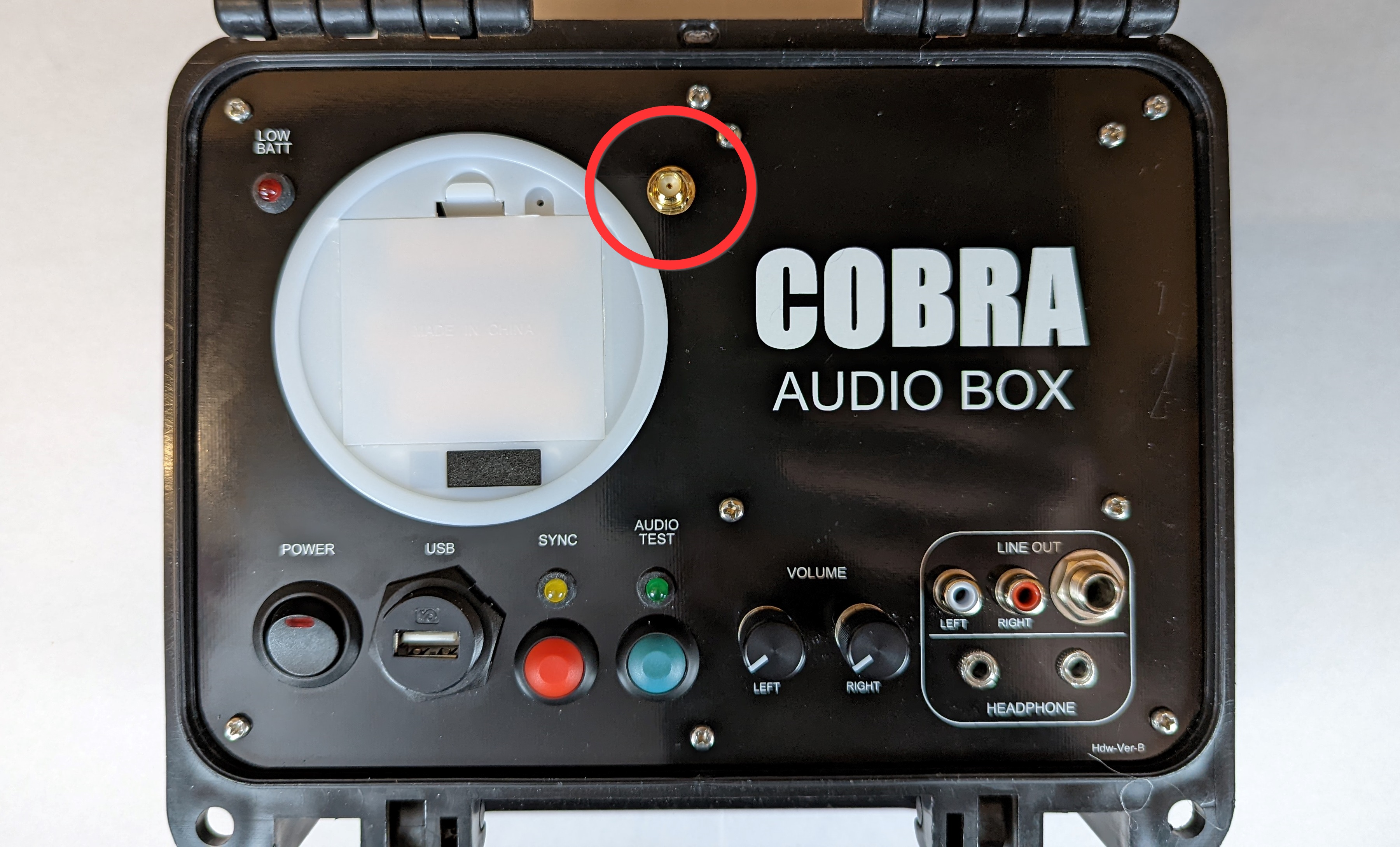
2. Remove the nut and lock the washer on the antenna SMA connector.
3. Remove the Audio Box from the armored case and turn the unit over.
4. Disconnect all of the harnesses from the back of the Audio Box.
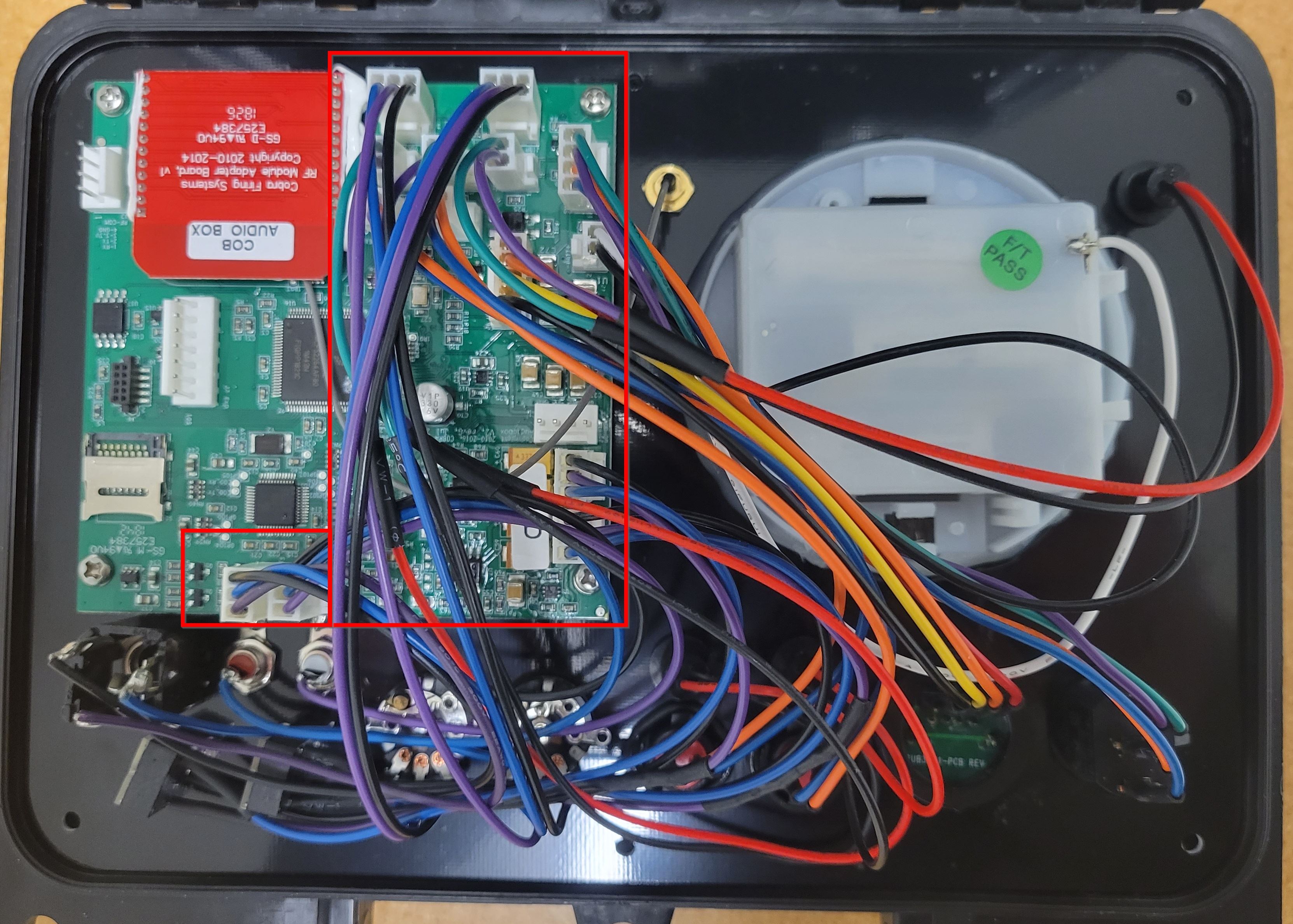
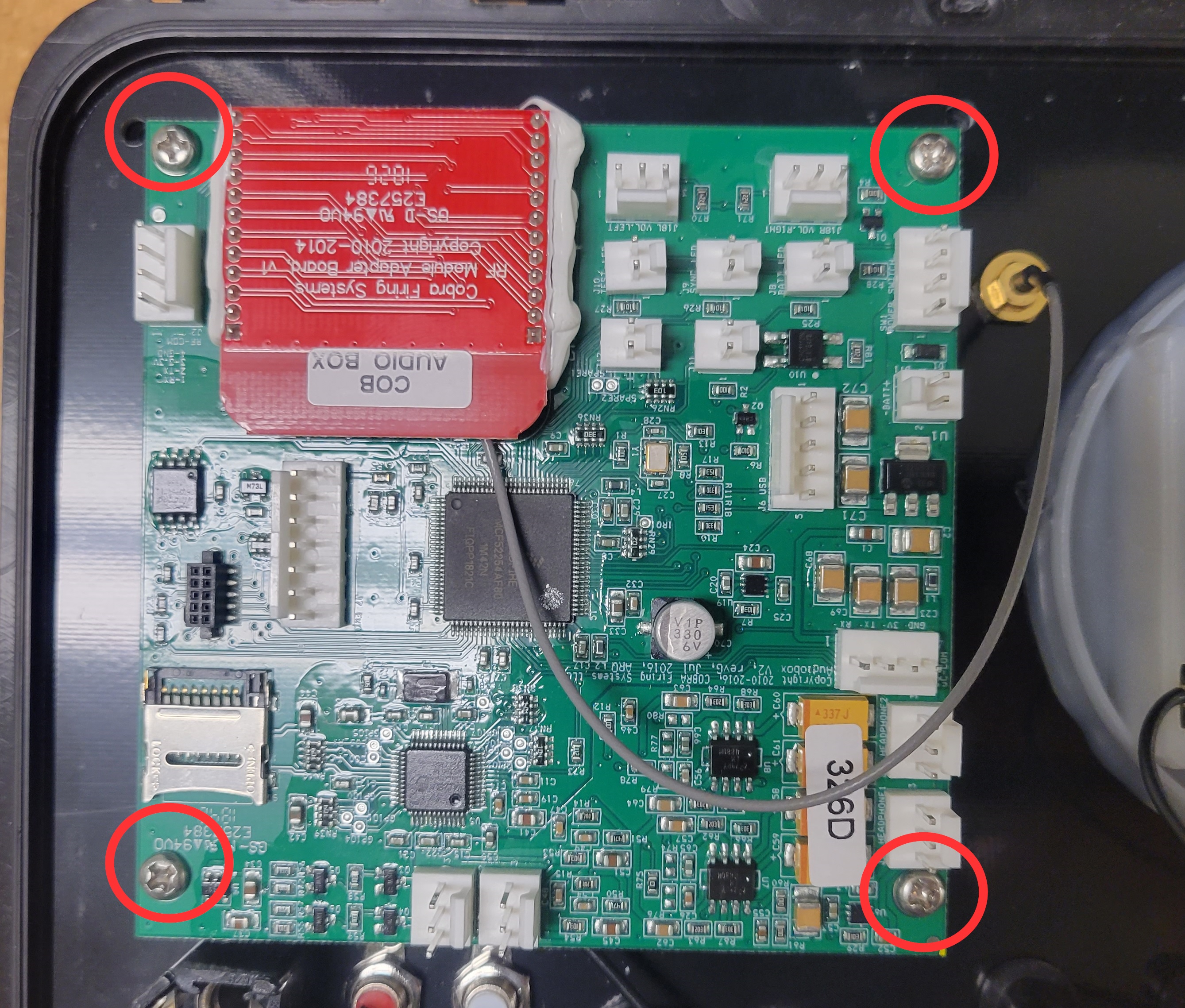
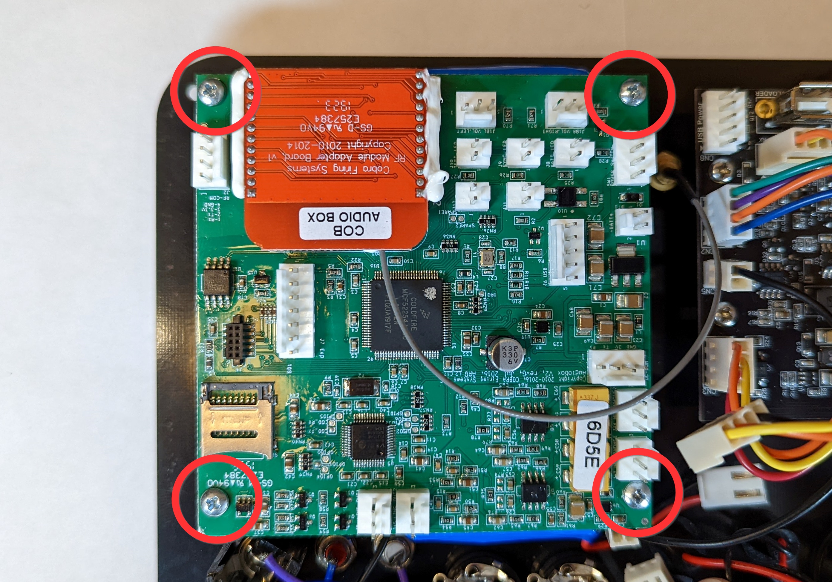
5. Remove the four screws on the Audio Box main PCB and remove the Audio Box main PCB. The old faceplate can be set aside.
6. Grab your new Audio Box LiPo kit and turn the unit over. Locate the LiPo battery and remove the adhesive strip backing.
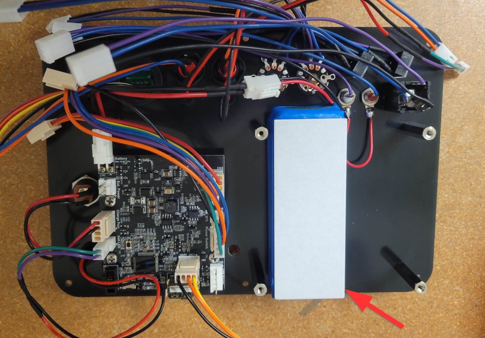
7. Align Audio Box PCB with four standoffs. Orient the PCB as shown in the image below and secure using the four screws included in the upgrade kit.
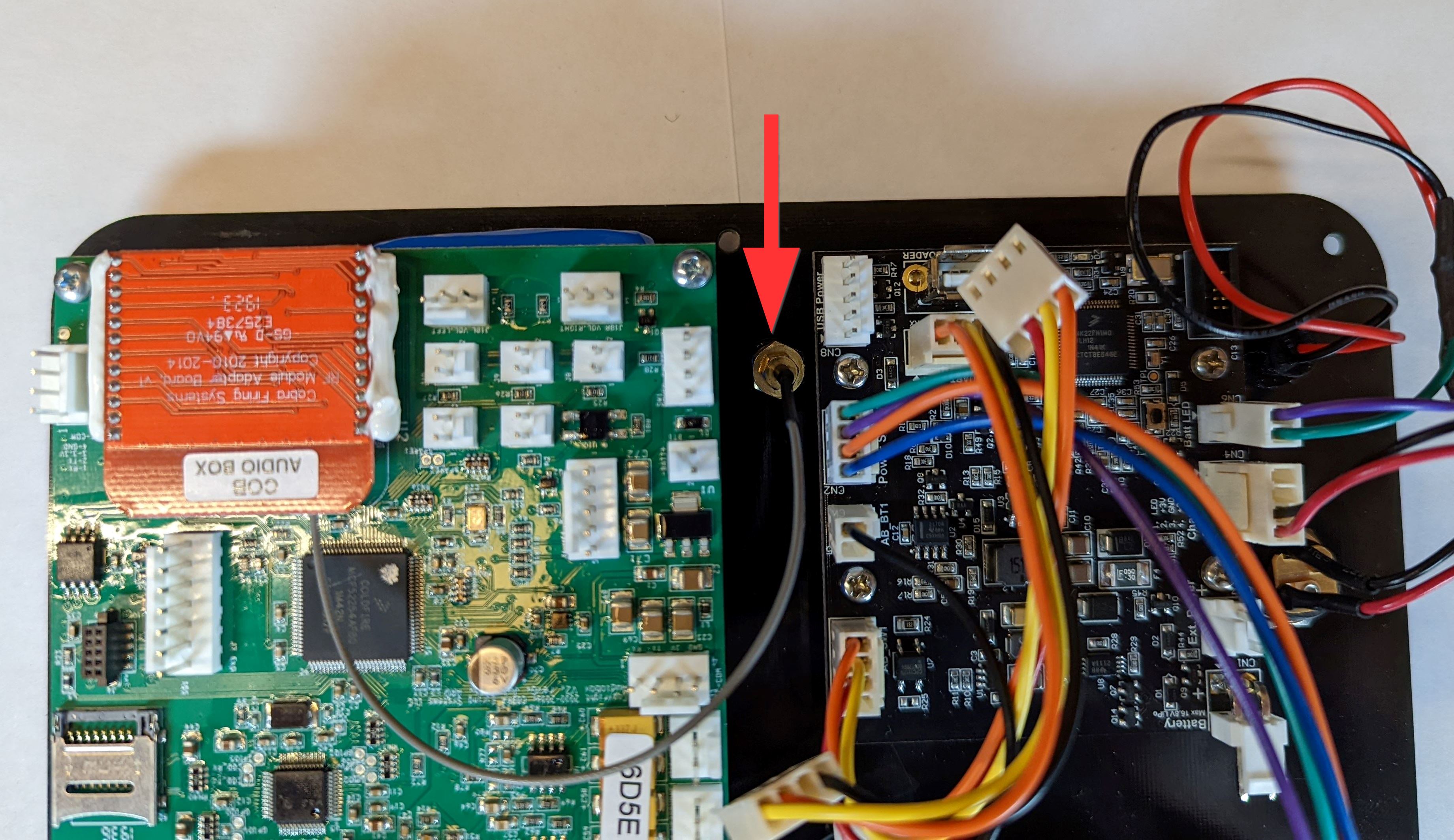
8. Insert antenna SMA connector into SMA hole. Turn the unit over and place the lock washer followed by the nut back on the SMA and use a 5/16" wrench to hand tighten.
Determine Audio Box Hardware
If you are using an Audio Box Hardware B version, determined by the red transceiver, skip to step 14 below. If you are using an Audio Box Hardware A version, please follow the steps to remove the power switch from your current Audio Box faceplate.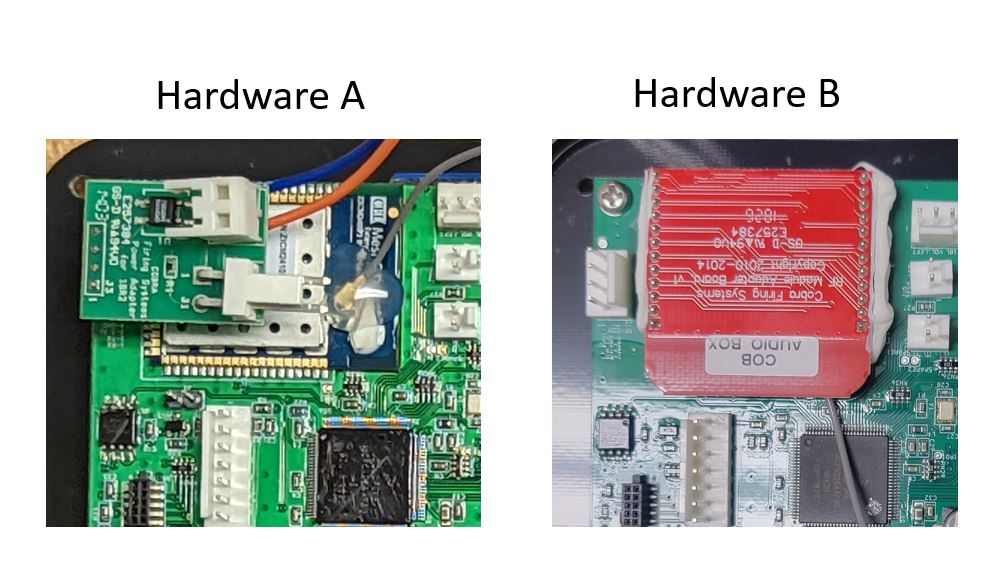
9. Using a flat head screwdriver push in and down on the tabs on the top and bottom of the power switch. Your power switch should be off of the faceplate now, but we need to disconnect some wires to free up the power switch harness from the faceplate.
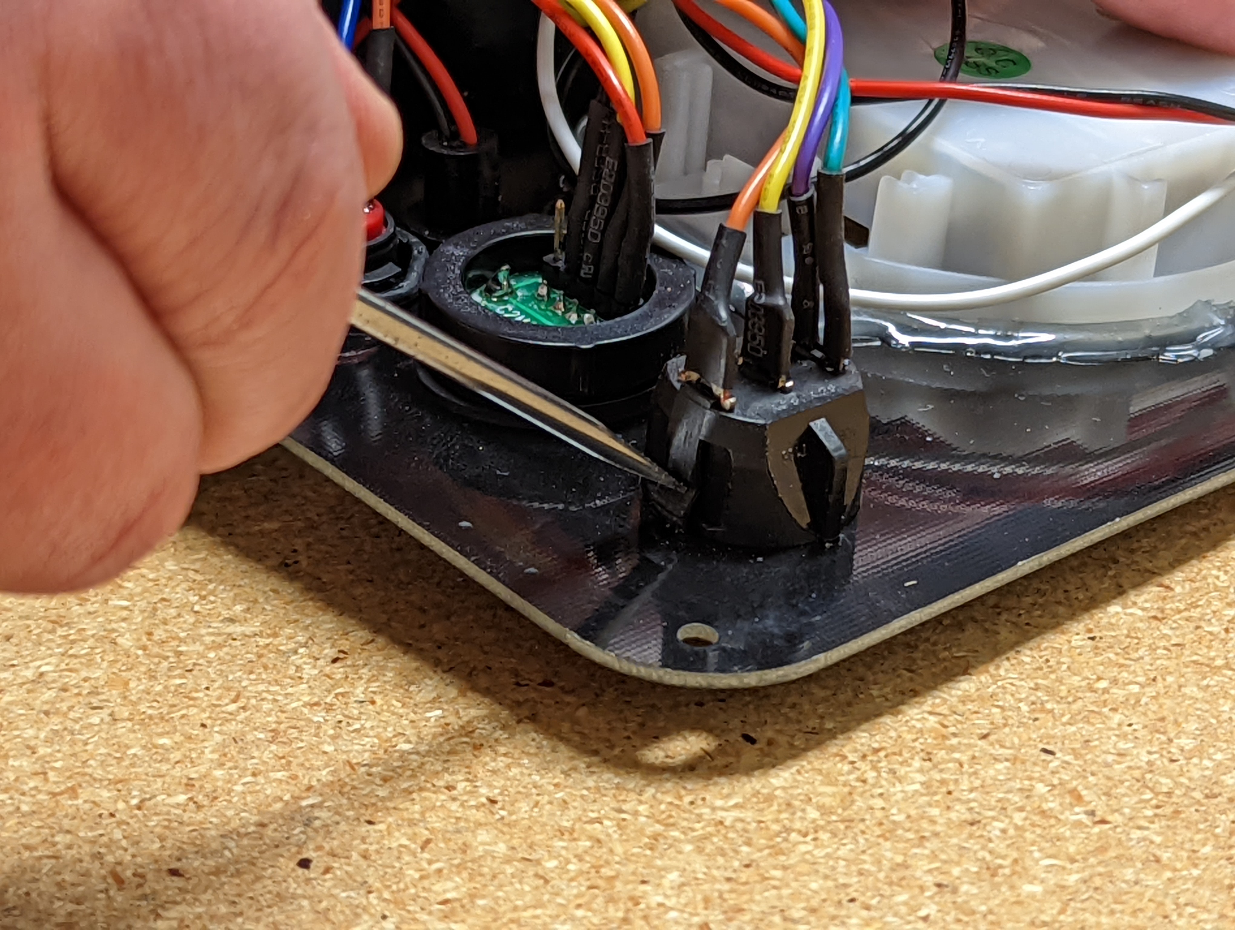
10. Remove the connector with the yellow and orange wires from the power adapter. Lightly press in the tabs securing the blue and orange wires and remove the wires from the connector. Completely remove the power switch and all wires from the old faceplate at this point.
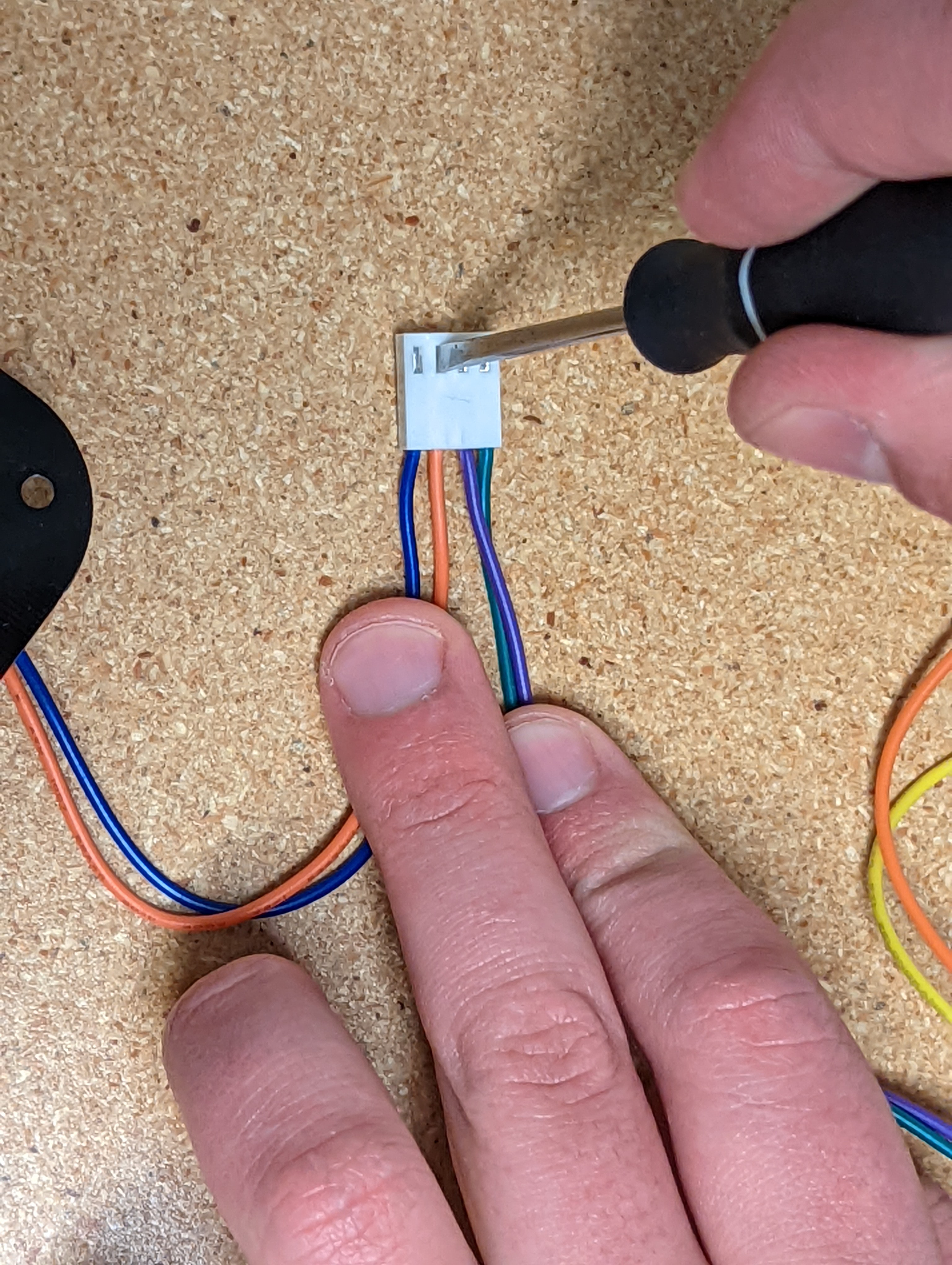
11. Remove the power switch currently installed on your new AB LiPo kit (same as step 9). Install the old power switch onto the LiPo kit faceplate.
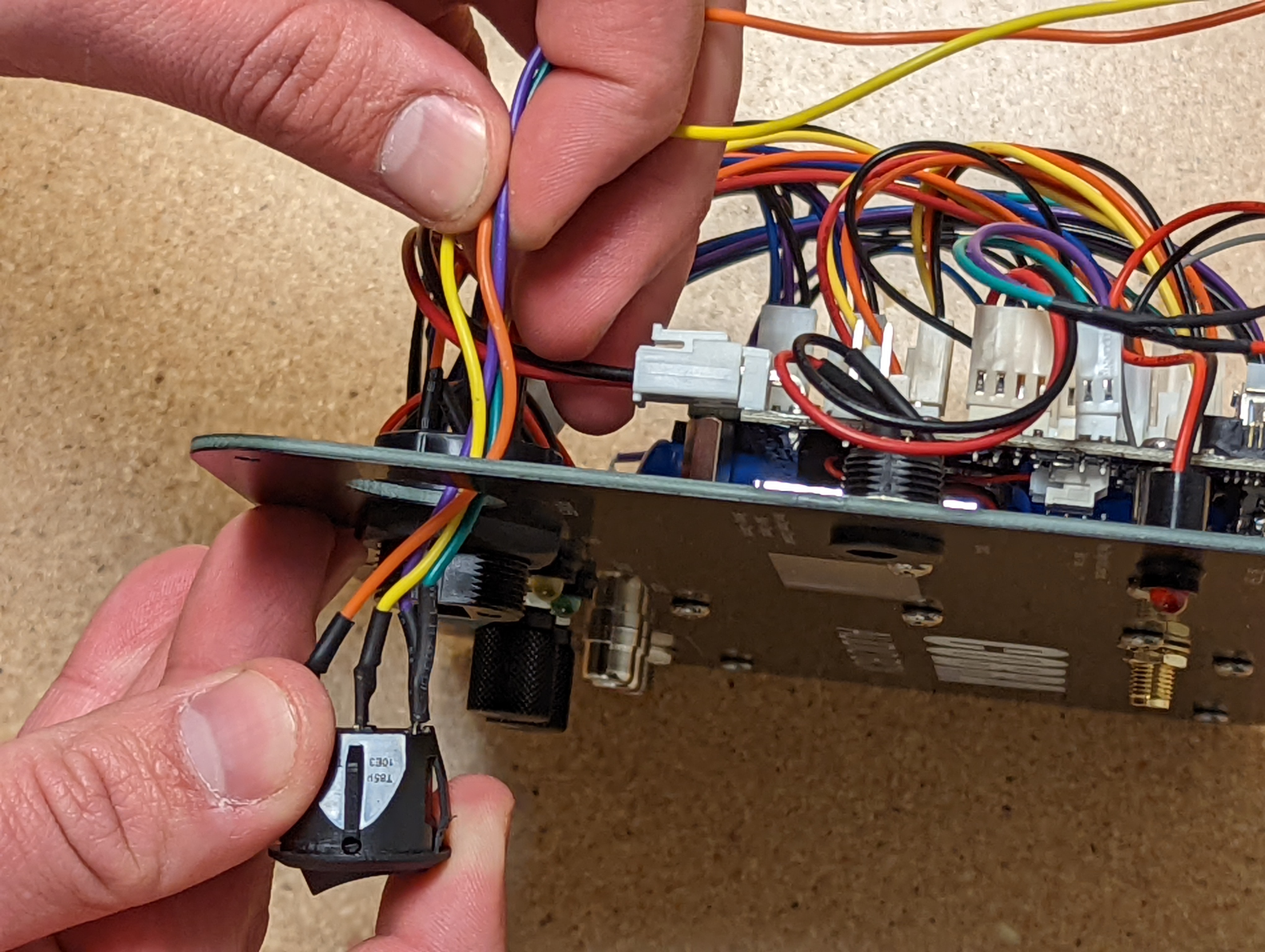
12. Reconnect the blue and orange wires you disconnected.
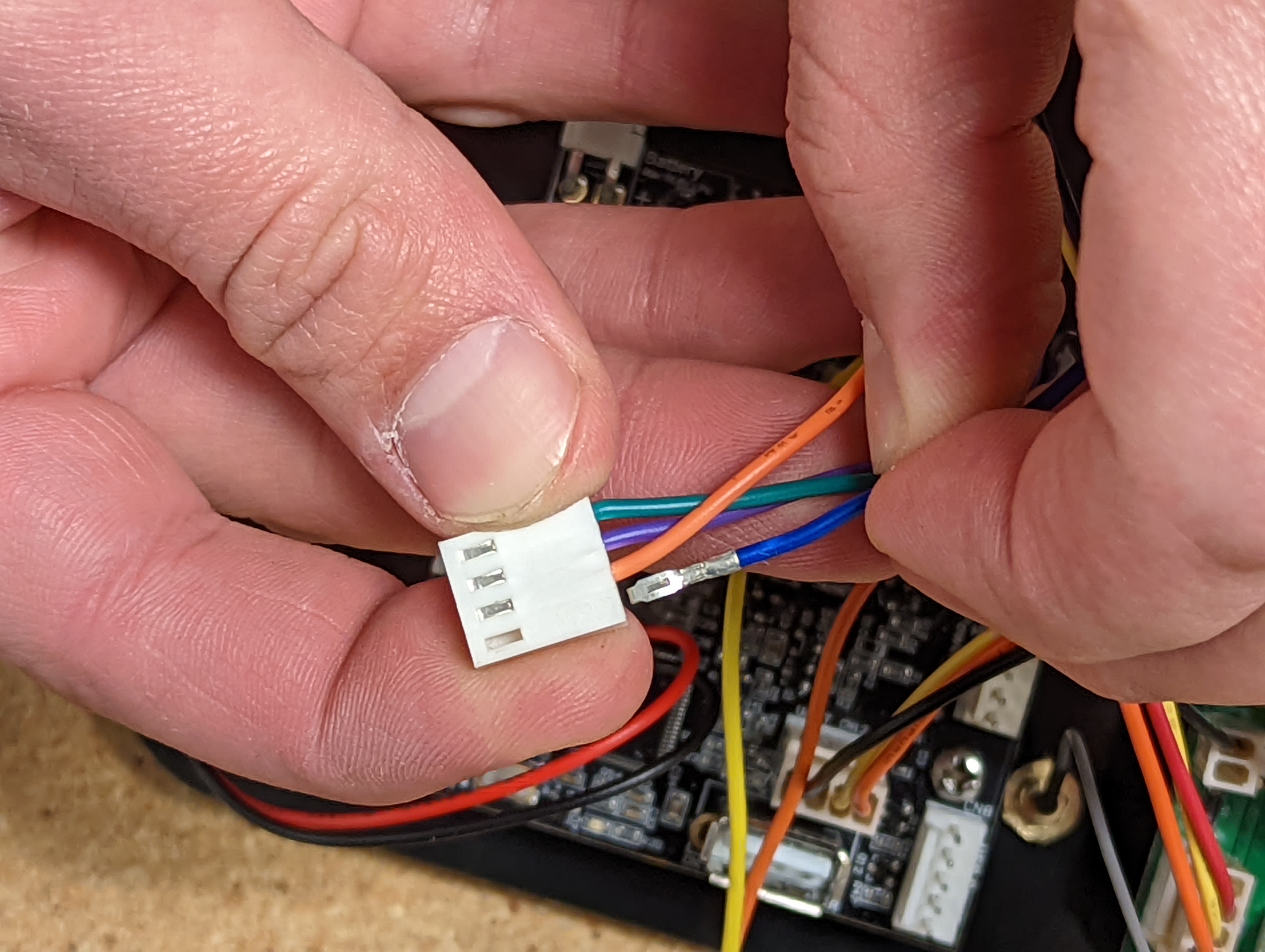
13. Connect the power switch to the LiPo PCB. Plug the power adapter into the Audio Box PCB. Reconnect the yellow and orange wires to the power adapter.
Your power switch is ready to go. Return to Step 9 and complete the rest of the steps to finish installing your LiPo upgrade kit.
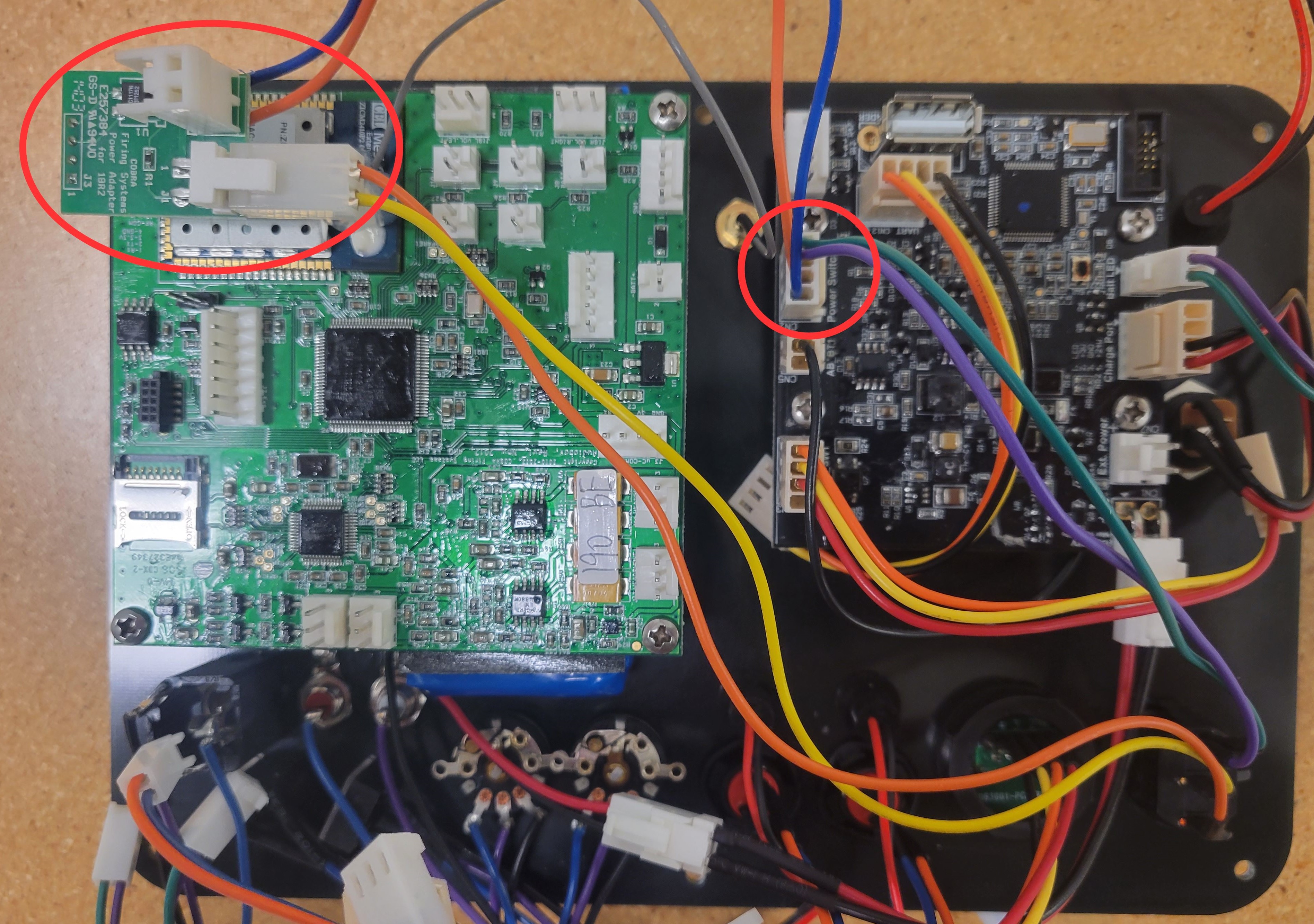
14. Connect the power harness from the LiPo PCB to SW1 Power Switch on the Audio Box PCB.
Audio Box LiPo Gen. 2
Audio Box LiPo Gen. 1
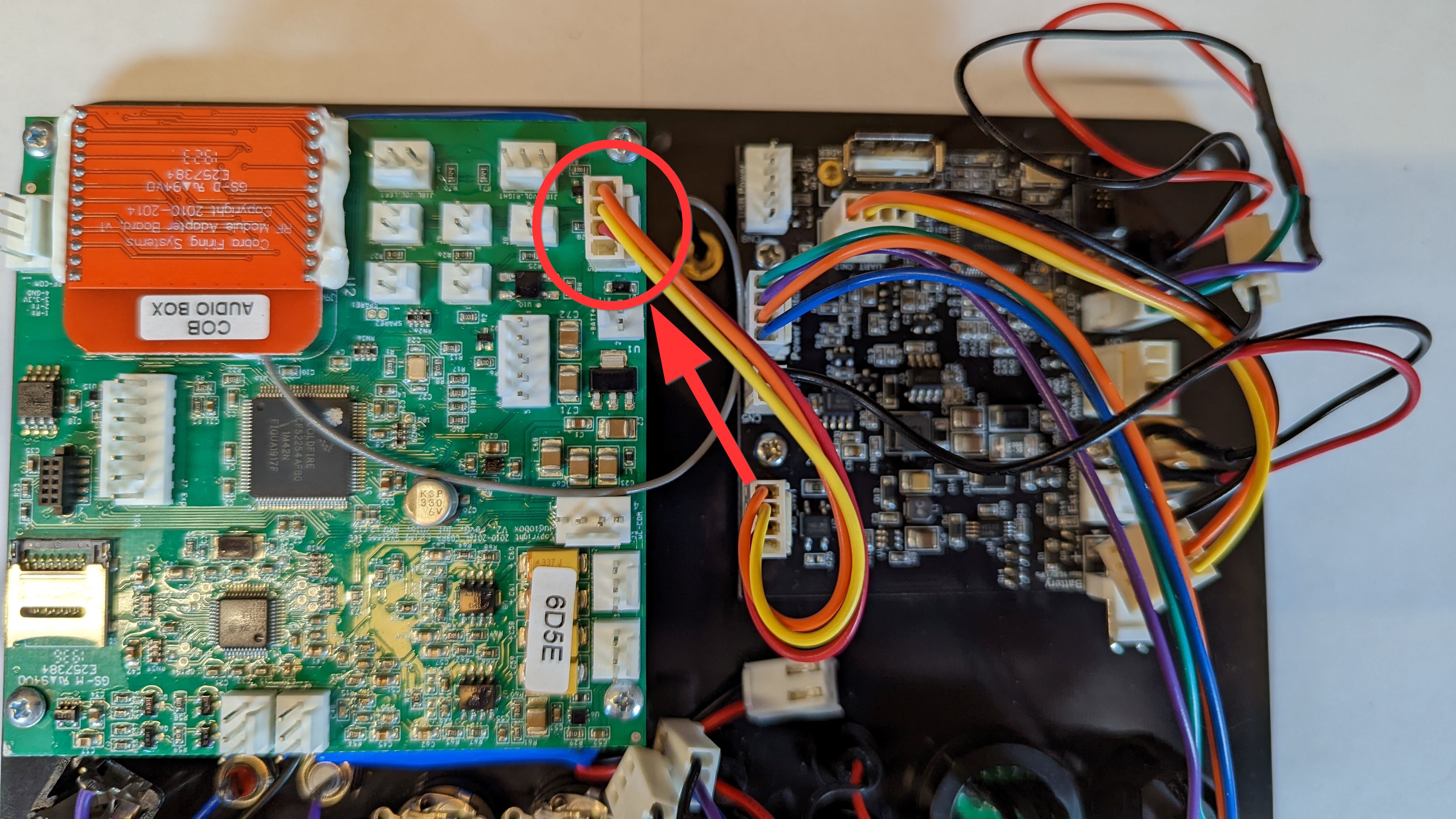
15. Connect the battery harness from the LiPo PCB to BT1 on the Audio Box PCB.
Audio Box LiPo Gen. 2
Audio Box LiPo Gen. 1
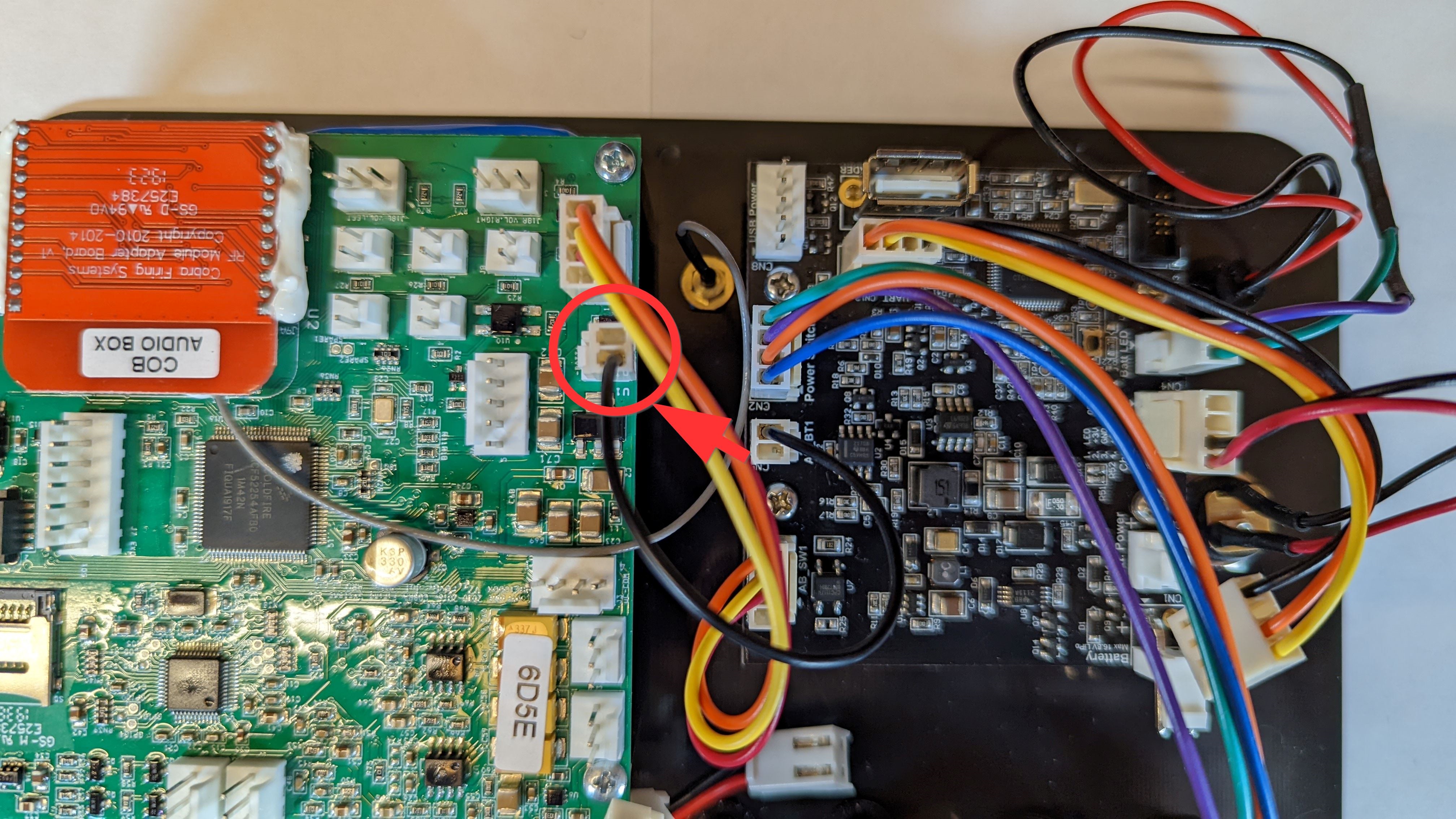
16. Connect the uART harness from the LiPo PCB to J3 on the Audio Box PCB.
Audio Box LiPo Gen. 2
Audio Box LiPo Gen. 1
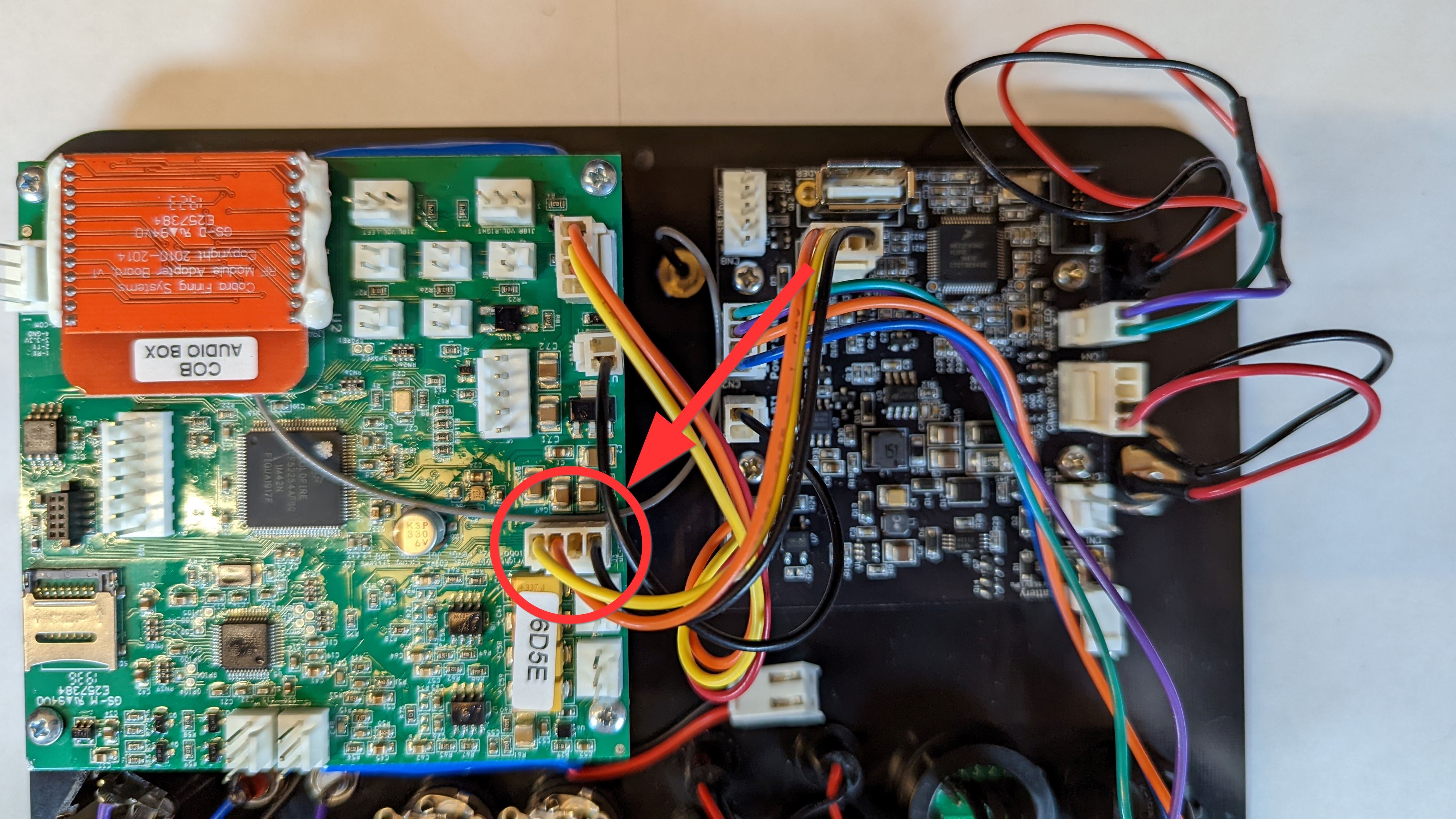
17. Connect the 1/4" jack harness to J5. If you have an XLR kit installed, skip this step as this port will connect with the XLR kit later in the assembly.
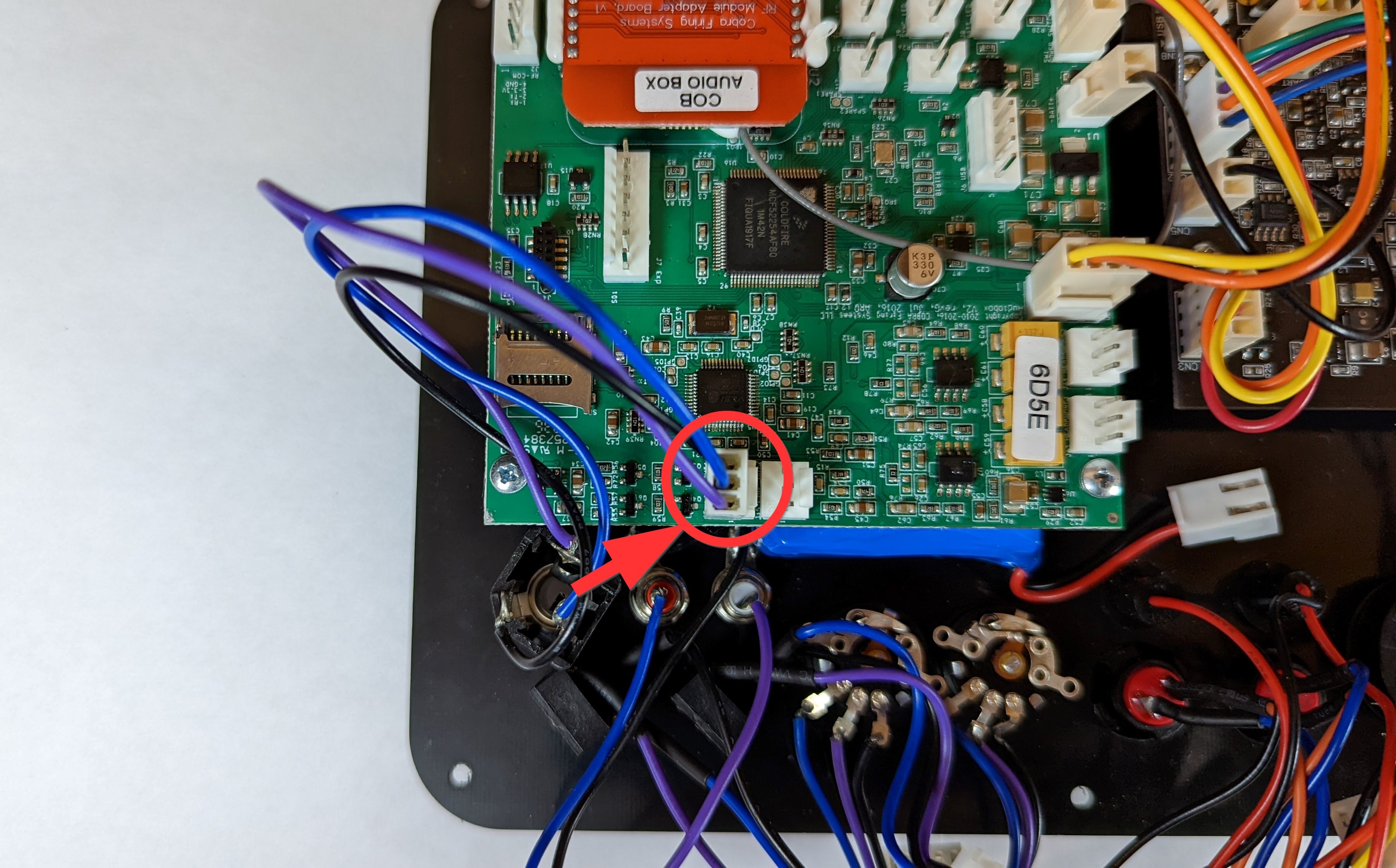
18. Connect the RCA harness to J15.
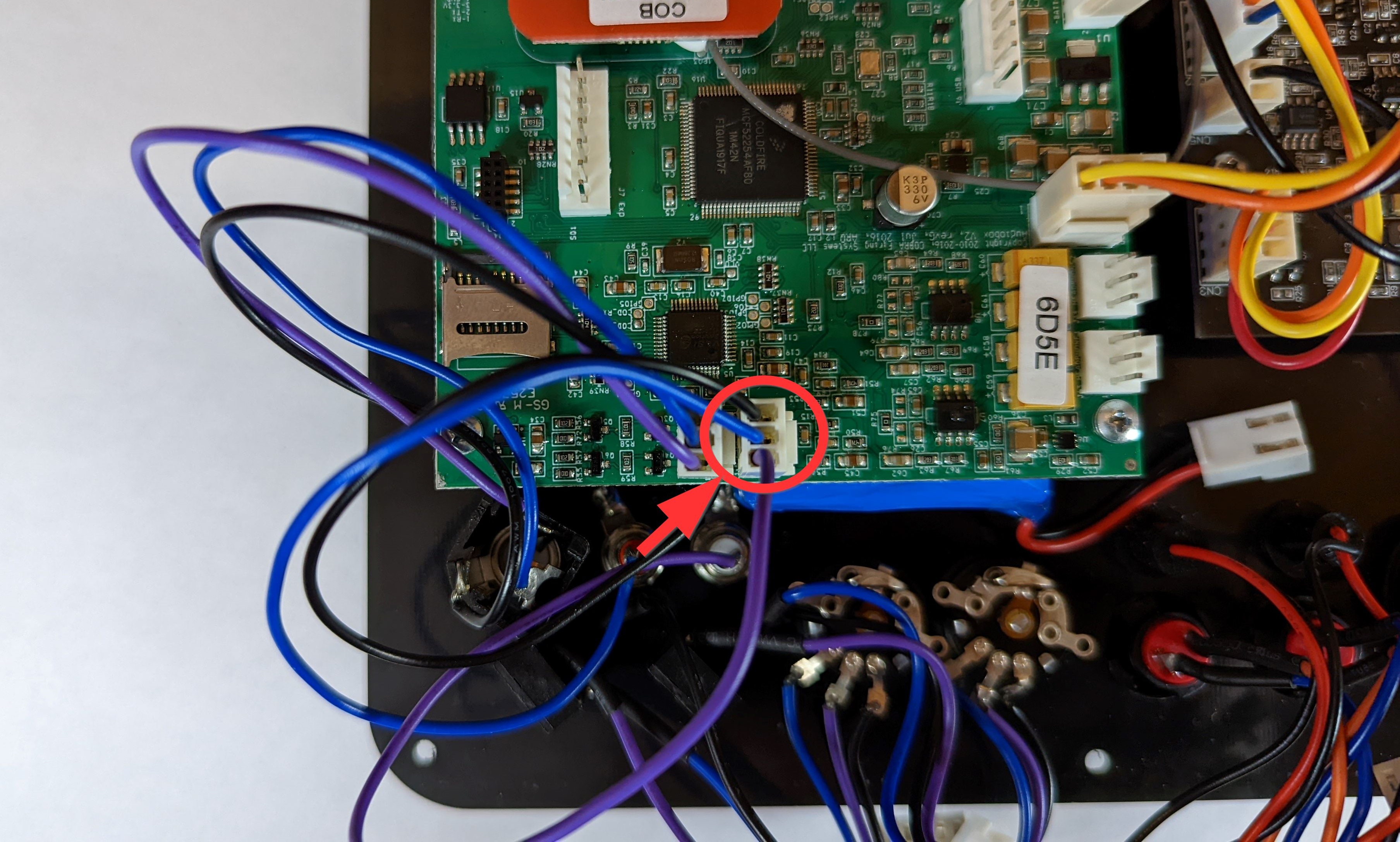
19. Connect the first 3.5mm Jack (Left on the back of the unit, Right control on the front of the unit) to J14.
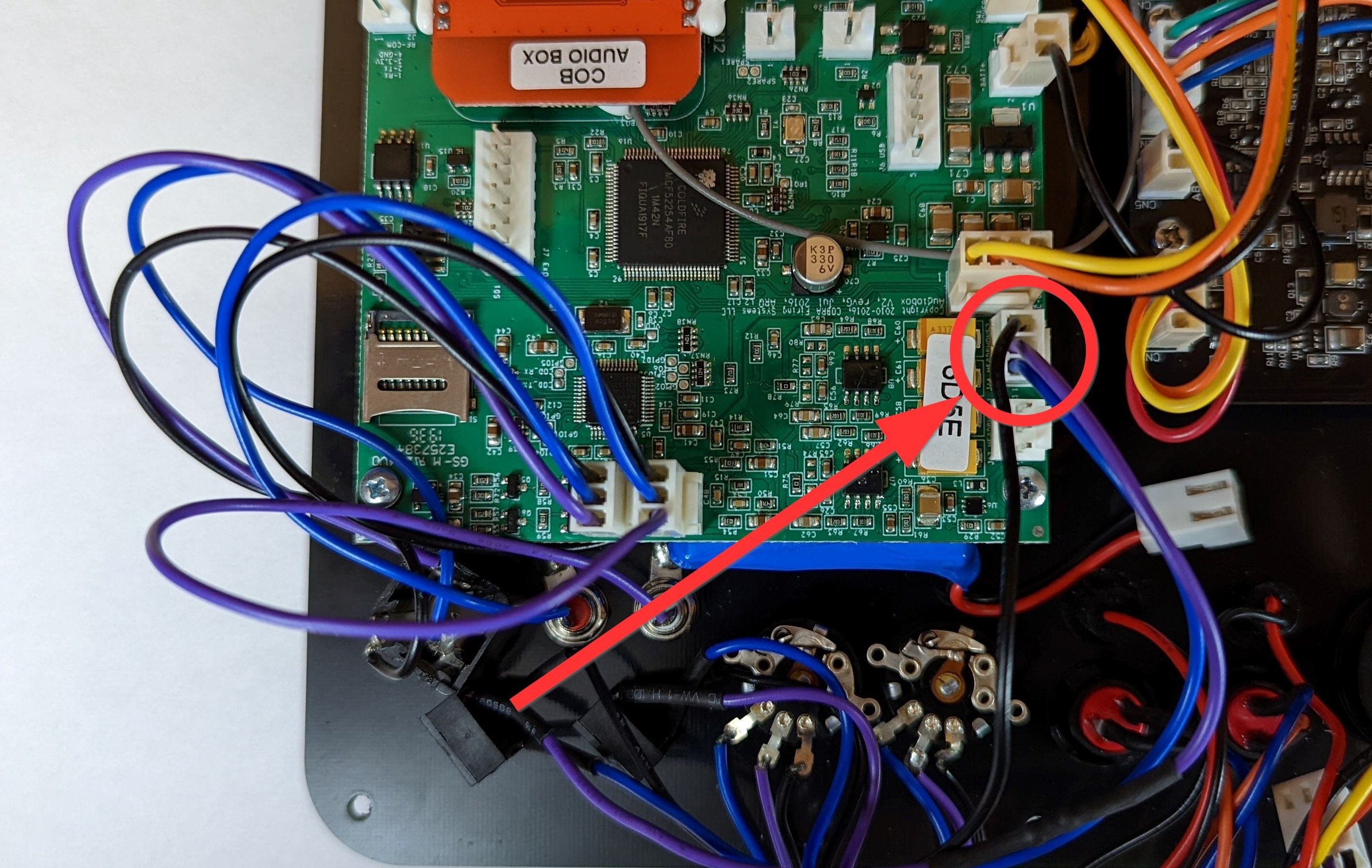
20. Connect the second 3.5mm Jack (Right on the back of the unit, Left control on the front of the unit) to J13.
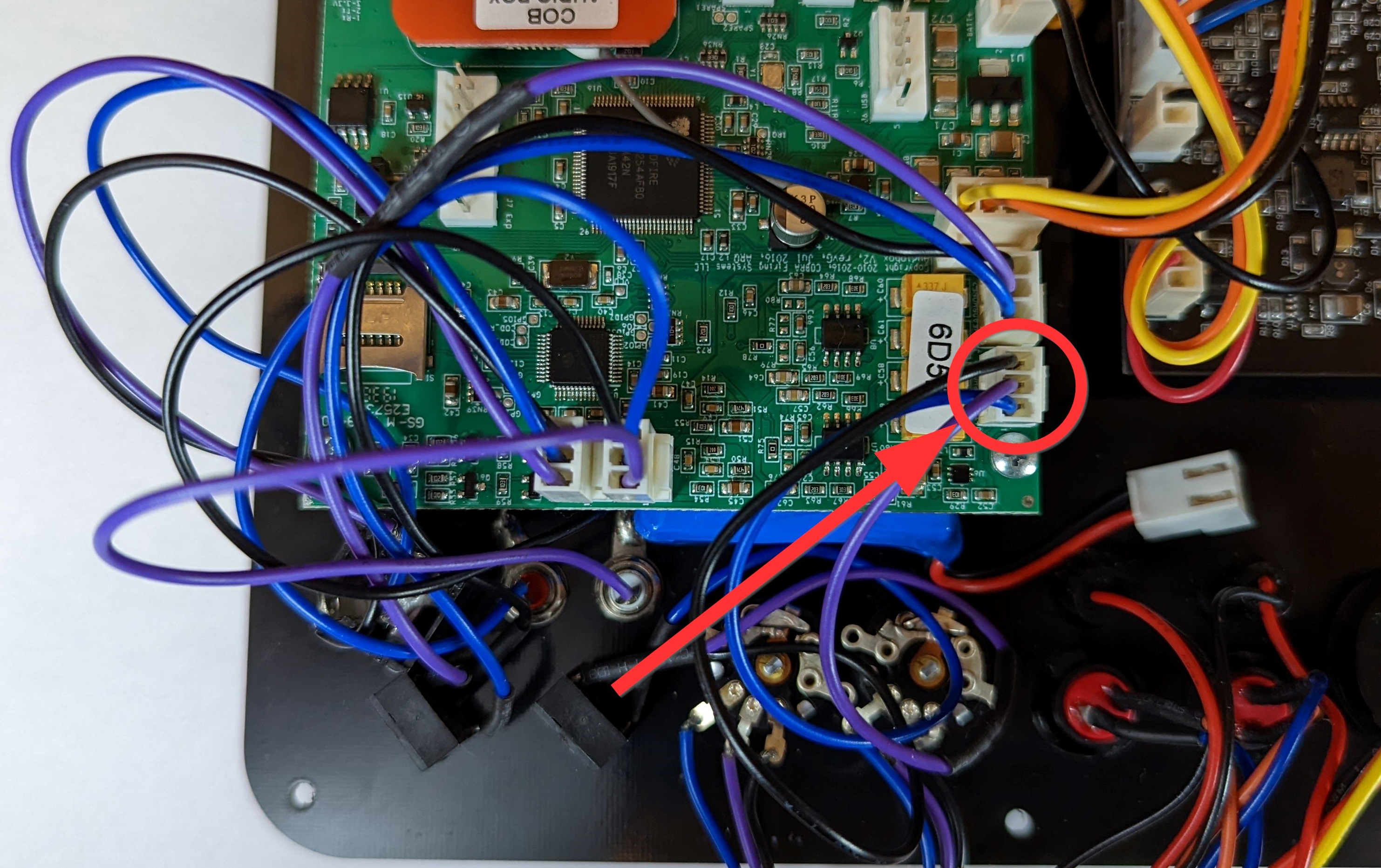
21. Connect the TEST Button to J12.
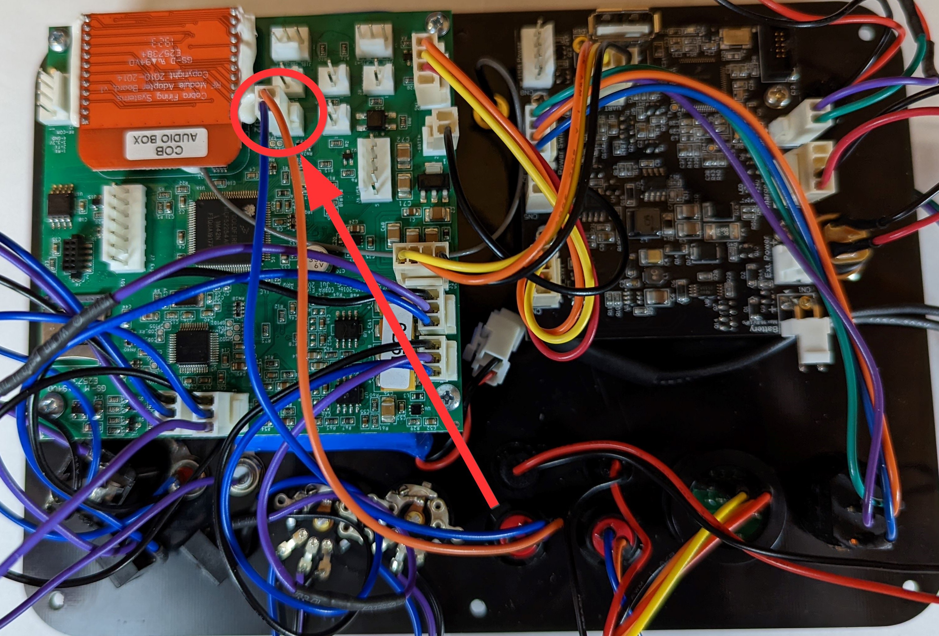
22. Connect the TEST LED to J10.
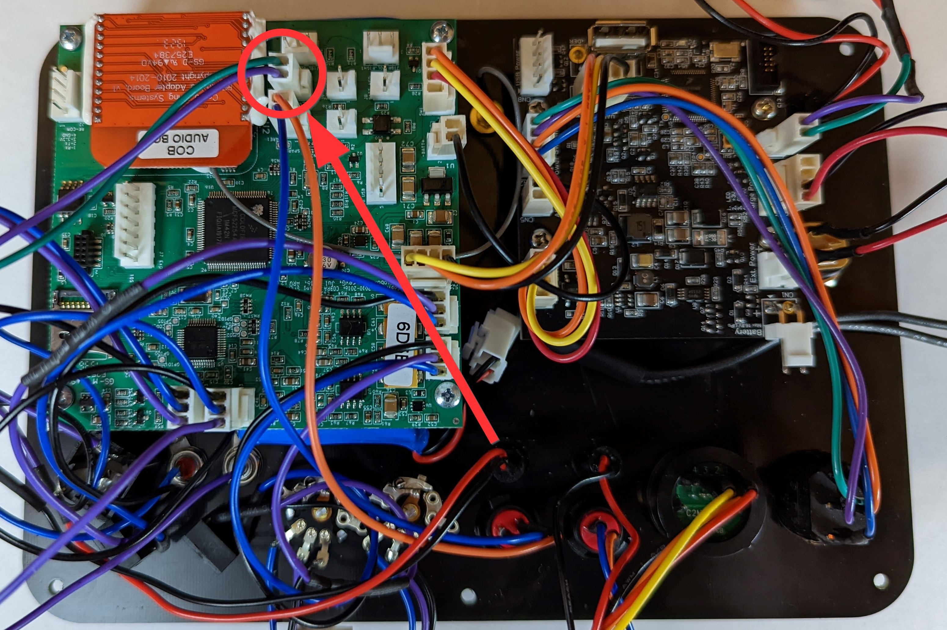
23. Connect the SYNC Button to J11.
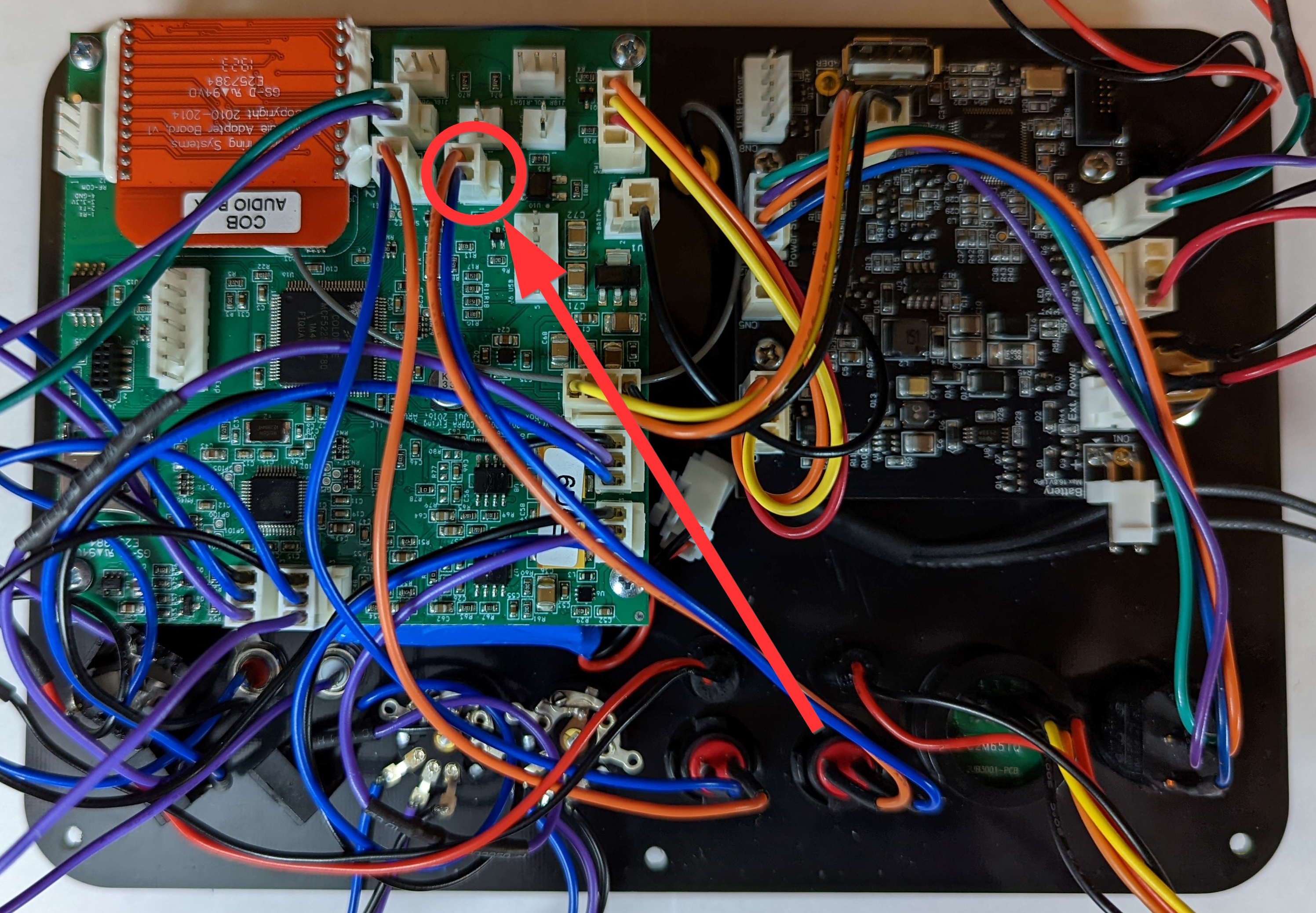
24. Connect the SYNC LED to J9.
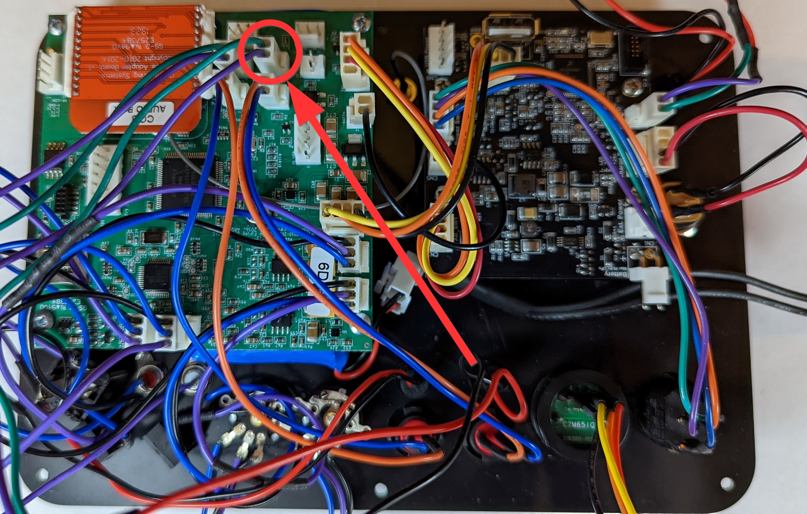
25. Connect the USB port to J6.
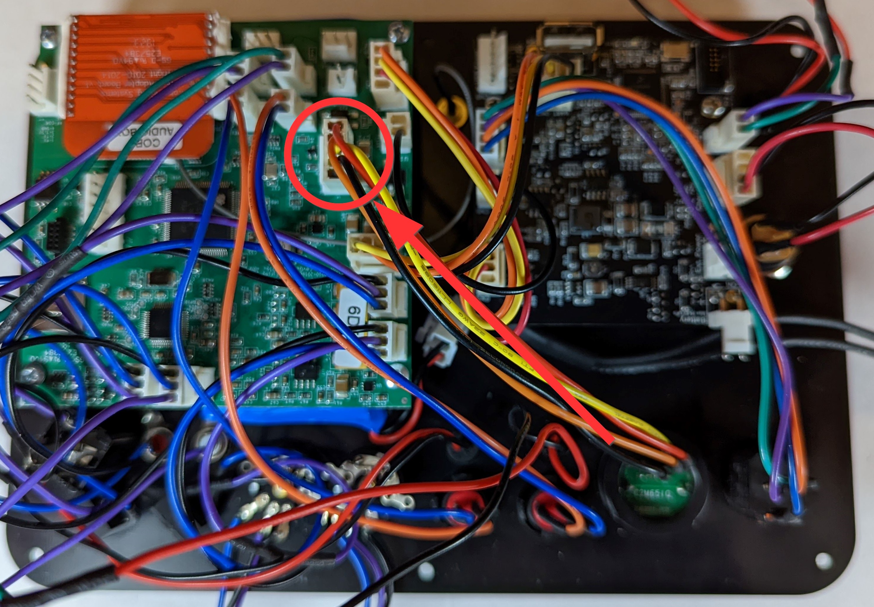
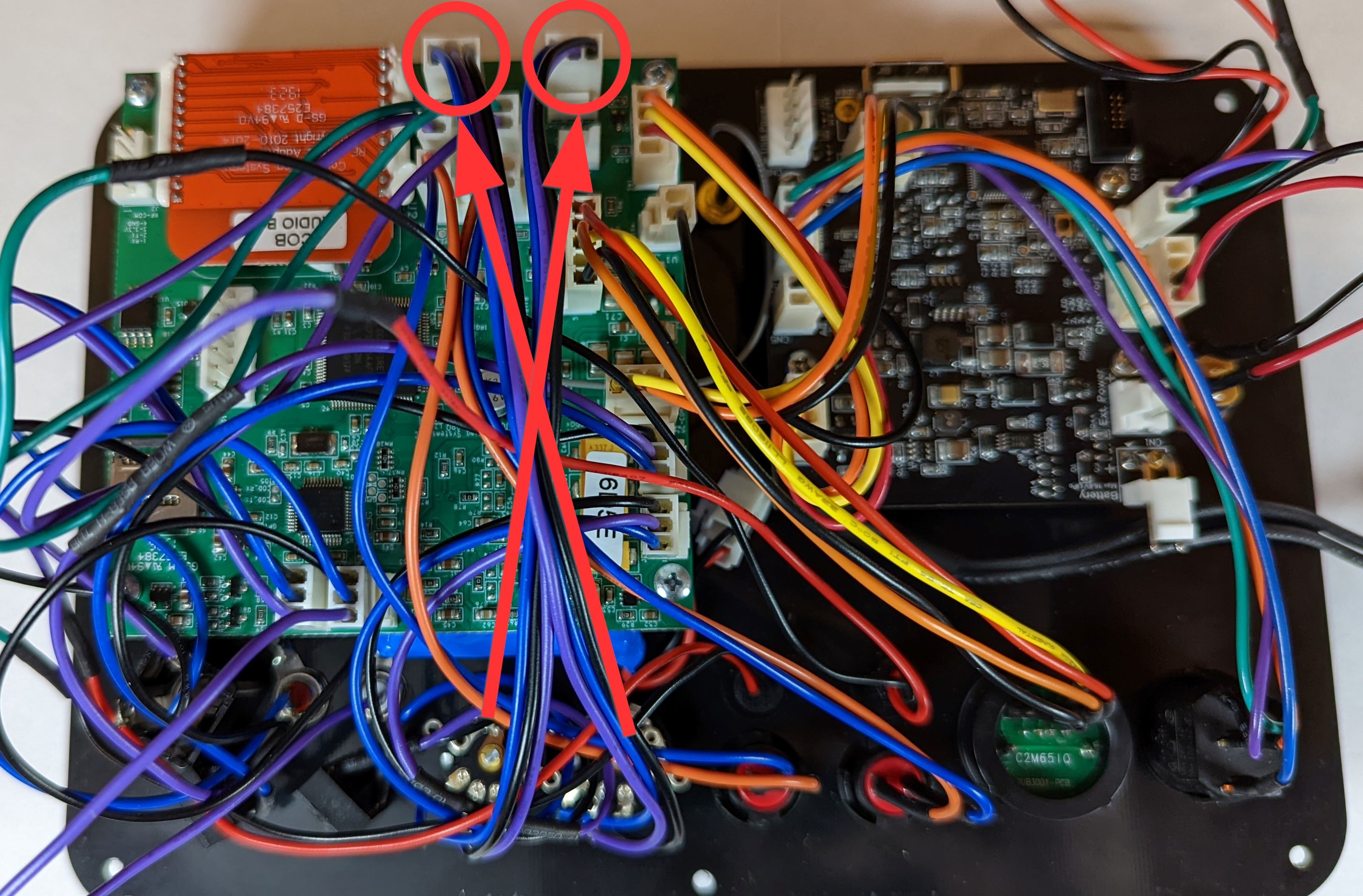
26. Connect the volume knobs to J18L and J18R. The volume knobs should cross so that the left knob is plugged into the right connector and the right knob is plugged into the left connector.
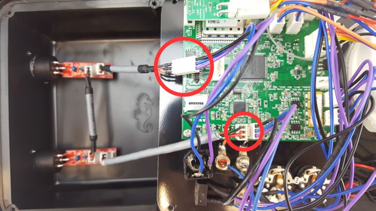
27. If you have an XLR kit installed, connect the 1/4" jack to the XLR harness and the other end of the XLR harness into J5 (refer to step 12). If you do not have an XLR kit installed, please continue to step 28.
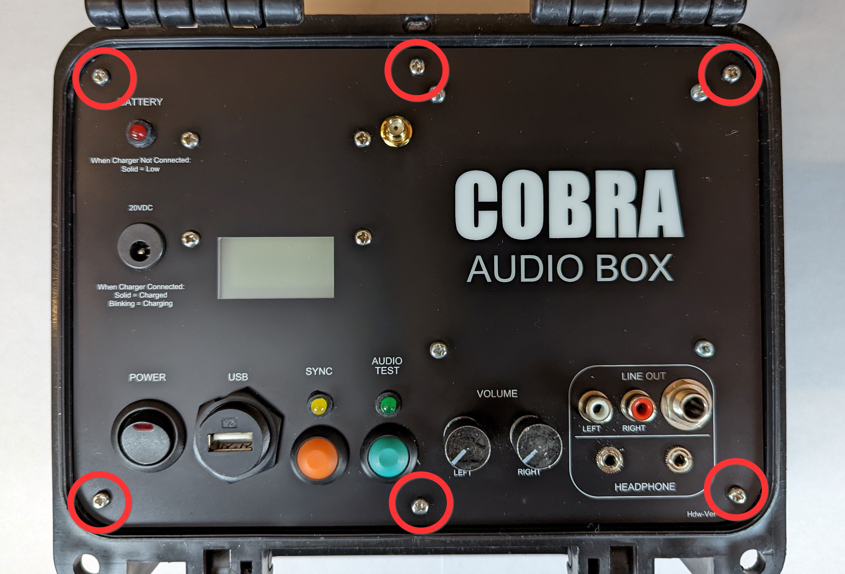
28. Place your new Audio Box LiPo kit into the armored case. Install the six panel screws that were removed in step 1.
29. Upgrade your Audio Box to 5.1.4 or 6.0.6. Refer to the following upgrade article. If you are already on 5.1 or 6.0, you only need to load the S19 file. Instructions to load the S19 file are below.
How to upgrade the Audio Box S19 only?
- Download the S19 file attached to this article for either 5.1.4 or 6.0.6.
- Move the S19 file to your USB Drive. Rename the file to "Audiobox.S19". If the file is not renamed, it will not load onto your Audio Box.
- Insert the USB Drive into the Audio Box while the unit is powered off.
- Hold the SYNC button and power on the unit.
- After the SYNC LED stops blinking, the unit should power on and display the correct version on the LCD.
Comments
Article is closed for comments.